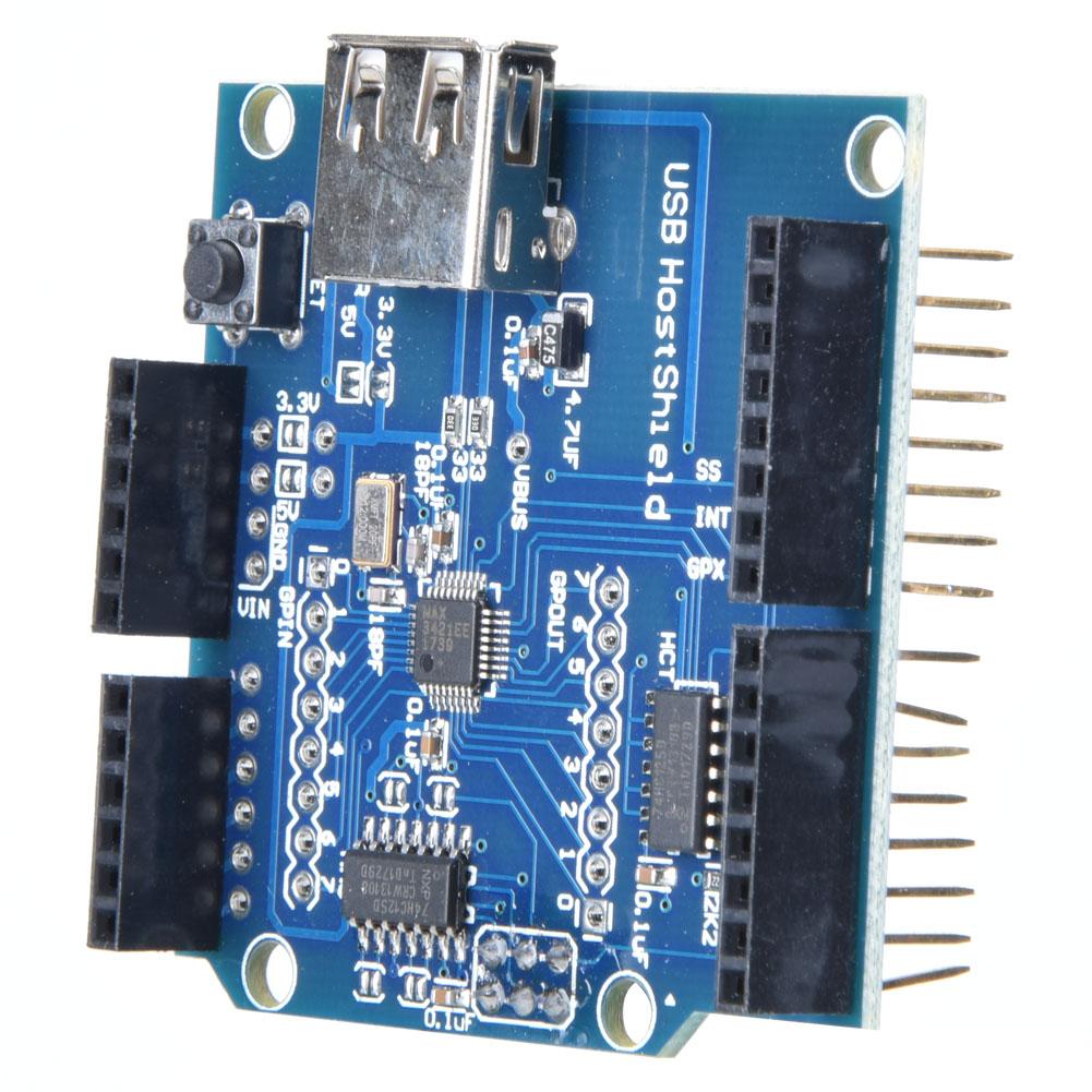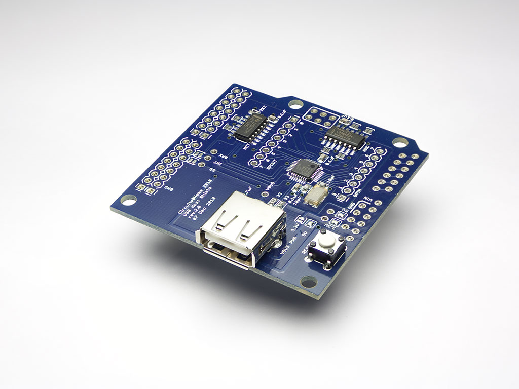

And finally, the MIDI I/O is from the Arduino's RX/TX pins: Connect +5V to RAW and ground to GND right next to it.Ĥ. Power is usually the red wire, ground is the black wire. Cut the mini/micro connector end off of a USB cable. The safe way would be to use pin headers but if you want it compact you can solder it like I did.ģ. Connect the 2 boards! The USB Host Shield can be on the top or the bottom. On the bottom side of the USB Host Shield, you can see how I pulled the wire through the GPIN 3210 hole and soldered it to the RAW hole:Ģ. if you want everything neat and clean, solder a wire to the VBUS hole on the top side of the USB Host Shield then solder the other end of the wire to the gpio (GPIN 3210) hole that's adjacent to the RAW hole. cut the trace or the jumper pad going to the VBUS pin

**** Credits go to this earlier tutorial. This requires installing a wire between RAW (5V USB input) and the VBUS pin: You need to set the VBUS to 5V instead of 3.3V. 6N138/6N137 optocoupler, 1N4148 Diode, 1K resistor (optional if you want MIDI->USB)ġ. 2x 220 Ohm resistors for the +5V and MIDI data outputs

TRS 3.5mm cable or 5-pin MIDI DIN cable Arduino Pro Mini 3.3V (Don't buy the 5V version!) I also can't guarantee it will work with every controller! This needs a MIDI controller that is USB Class Compliant. Here's a DIY version that costs about $10-15 via eBay: There are some decent professional USB MIDI hosts that are currently available, but they're kind of expensive. thanks in advance, felis.A lot of us still have devices that only have MIDI DIN connectors, yet many MIDI controllers these days only have USB connectors. Hope u can help me out regarding this issue. I have been trying different approach like supplying direct 3.3V to the reset pin of the USB host shield and tried toggle high to low and back to high to one of the dev kit pin to the reset pin of the usb host shield but yet still got same OSC did not start. on my serial is shown description of the USB device which is attached to it.īelow is the picture of arduino nano connected to the usb host shield. below is the screenshot of my serial monitor.Īt the first place i thought the usb host shield might be broken or damaged. While for the RST i connected it to EN pin of the DOIT ESP32 Dev Kit V1.įor the power, 5V is supplied only to the VBUS (the MAX3421E is supplied by 3.3V)įYI, i using USB_desc example code however, on my serial monitor showing OSC did not start. GPIO5 : SS, GPIO17 : INT, GPIO18 : SCK, GPIO19 : MISO, GPIO23 : MOSI i did the connection as in the commit a7f67cd i tried to use USB host shield with DOIT ESP32 Dev Kit V1.


 0 kommentar(er)
